3d Max Materials and Material Editor (Material Editor)

So, what materials and what are they for? Proceedings of a set of different visual properties of an object, such as color, transparency, texture, reflection and refraction properties of light, etc. How likely it is clear from the description of the materials needed to make it more realistic targets. To work with the materials in 3ds max there is a special module called Material Editor (Material Editor).
Start 3ds max, if you have not already done so. Now you have to open the Material Editor. The easiest way to do this press the «M» at the keyboard, but you can from the main menu - Rendering → Material Editor ... should open a window here:
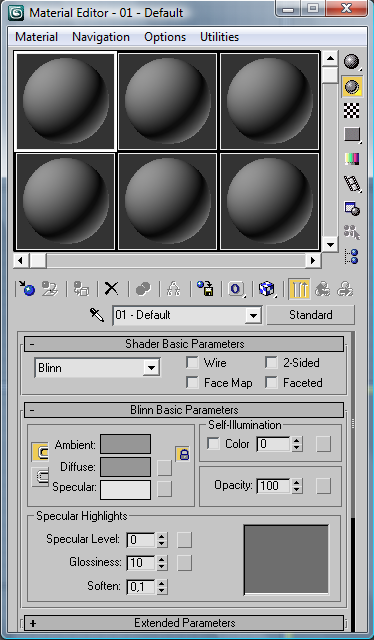
At the top of the editor you can see the six gray ball. This is a sample of materials, by default, they are gray in color. To change the material must select a cell with this material, this should click the left mouse button on the cell. Selected cell has a white border, in the above figure dressed upper-left cell.
If you right-click on the selected material will open a context menu:
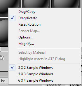
It has the following features:
Drag / Copy - Copy of the material to another cell;
Drag / Rotation - rotation of the material in the cell;
Reset Rotation - produced by removal of the rotation;
Render Map - allows you to visualize the texture map which is based on the material;
Options - opens the window Material Editor Options, where you can assign a different setting of the material editor;
Magnify - opens the selected material in a separate window when the window stretched the material is stretched, too, so this tool can be viewed as a tool to increase the sample material;
Select by Material - allows you to select all objects in the scene using the currently active material (duplicates one of the tools described below).
3 X 2/5 X 3/6 X 4 Sample Windows - changes the amount of visible material. By default, the editor shows six samples of materials (2 rows by 3 columns), it can be exchanged for 15 samples (5 X 3) or 24 (6 X 4).
Under the cells and the right of them are tools for working with materials. The following is a description of these tools, some of them may not seem obvious, do not worry, many of these tools will become clearer in the process of learning the following lessons.

Sample Type - allows you to change the type of sample material. That is, instead of the ball can be placed in the cell cylinder or cube. Yet usually more convenient to use the ball.

Backlight - allows you to toggle on and off the light source behind the material. By default, the light is turned

Background - change the cell background. The default background color of the cell dark gray, but if you click on this button to turn the background to the checkered black and white background. This tool is often used when creating a transparent material.

Make Preview - allows you to view animation sketch material.

Options - opens the Material Editor Options, where you can adjust the parameters of the material editor.

Select by Material - allows you to select all objects in the scene using the currently active material.

Material / Map Navigator - opens the Material / Map Navigator, showing what materials and texture maps used in the scene.

Get Material - allows you to open the finished material from the library materials, or create a new

Put Material to Scene - allows you to make changes to the material objects in the scene, to which the material is applied.

Assign Material to Selection - allows you to use the current material to all selected objects of the scene.

Reset Map / Mtl to Default Settings - resets all the settings of the material, putting all the defaults.

Make Material Copy - after clicking on the button changes the parameters of this material does not cause changes in material objects in the scene. To apply the changes, press the button Put Material to Scene.

Put to Library - puts the material in the library materials.

Material Effects Channel - allows you to associate the material with one of the 16 channels of image effects used in video editing.

Show Map in Viewport - allows you to see how the vygledyat objects with texture in the viewport.

Show End Result - shows the final form of composite material.

Go to Parent - allows us to go to change the subobject level to a higher level to edit a parent object.

Go to Sibling - allows you to move to a change in the next sub-object, not rising to the level of the parent object.
Next is a tool Pick Material from Object (pipette in common):

It allows you to load in the current cell taken from a sample of the material object in the scene. To do this, after selecting this tool click on the desired object scene.
Next to the pipette is a dropdown list with the names of materials:

in this list, you can change the name of the current to do this, simply click on it and type a new name.
And finally, the right pipette and the name of the material to be key to the type of material, the default type of material Standard:

Clicking this button opens a window Material / Map Browser:
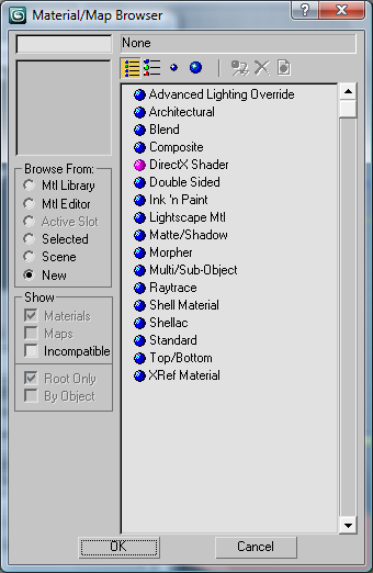
In which you can select the type of new material (in this box, you can not do only that, but in this case we are interested in a new type of material). All new types of materials are marked with blue balls in the picture, a description of each type would take too much time and will likely require a separate lesson. Therefore, to describe them is not going to, and focus on the most frequently used type Standard.
The following types of materials under the button to be a roll:
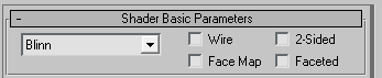
It deserves the most attention the way a shader, you can choose from the drop down list, such as how to do shading Metal surface of an object more like a metal.
Depending on which mode is selected shading change the scroll below, here's what it will look for ways to shading Phong:
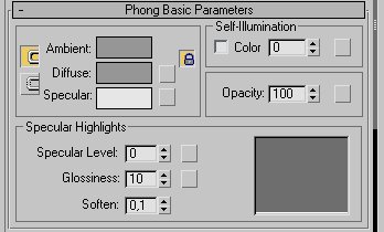
There are the following:
Ambient - determines the color of light, or as they say around the light.
Diffuse - defines a diffuse or scattered light coming from the material. By default, a change in one of these two colors is the change of the second, to avoid this, you should click on the button next to the names of colors:

Specular - determines the color of the light reflected from it you can set the color of the highlight.
Specular Level - specifies the "strength" of the flare, ie, on how much the surface reflects light.
Glossiness - will determine the "gloss" of the object, or the size of the flare, generally smoother than the material should be, the more and smaller patches on it.
Soften - determines the fuzziness of the material.
Self-Illumination - determines the level of self-illumination of the material, if the tick Color, then we can determine the color of light emitted.
Opacity - defines the transparency of the material, 100 (opaque) to 0 (fully transparent).
In the simplest embodiment, each of the parameters is controlled only by what is in one color, but this is often not enough. Sometimes you want to use the more complex the variation of the parameter, this close to so many parameters are such buttons, boxes:
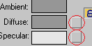
After clicking on these boxes opens a window Material / Map Browser, where you can set a procedural map that will determine a law to display this parameter. For example what happens if you set the diffuse color map of the procedural Gradient:
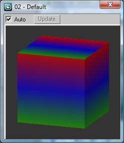
After such an appointment on a square next to Diffuse gets an «M»:
When you click on that you can configure the procedural map (in this case the gradient).
Consider the same roll of Maps:
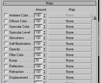
It describes all of the cards that can be used in this material. As you can see there are repeated many of the parameters described above. In fact it is just a duplication of those buttons, tiles, if not more options, such as Bump, Reflection, Refraction, etc., which in the Basic Parameters rollout, no. For these parameters can also be assigned its own procedural maps.
There are many kinds of procedural maps:
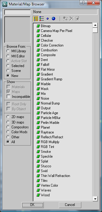
All of their paint no sense, many of them can be understood by the name, or simply applying to the material and change some settings. Some of these cards will be further discussed in the following lessons. Now let us consider the most important in my view a map that is used in one way or another if not all, in many materials.This is a Bitmap. It allows you to download and use as a card image file in any supported 3d max format (eg, png, jpg, gif, etc.).
If you apply a map to the diffuse color of a particular form of get this card, called a texture. That is, after applying the texture of the object as it painted a picture of the structure of this
For example, here the piano without the texture of the tree:
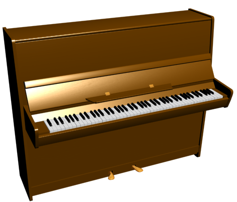
And with the texture of the tree:

As you can see, the texture can greatly change the perception of the object, which is why it is so important.
But here there is a small problem like a flat image of the object put on the volume? To come up with this so-called texture coordinates. Now try to explain the principle of their action.
As you probably remember all the objects in 3d max consist of triangles, each triangle has three vertices, each vertex has its own three-dimensional coordinates - X, Y, Z, and even texture coordinates - U, V (sometimes used more and W). Thus, any triangle can be with these two coordinates can be transferred from the three-dimensional coordinate system in two-dimensional coordinate system.
Each downloadable card is placed here in a coordinate system
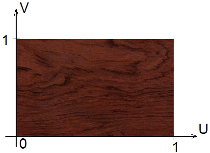
In the same coordinate system placed the triangles of the object, since each vertex is also assigned to these coordinates:

As a result, each triangle has the ability to place inside a piece of the image defined by the texture coordinates of its vertices:
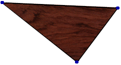
Most often, the texture coordinates of the vertices lie in the interval between 0 and 1, but sometimes they do more than one. In this case, the texture on these triangles starts to repeat itself, or as they say, "talitsya."
That's probably all I wanted to tell you about the materials. Perhaps it is understandable that is represented here only general information about the materials in more depth, we consider this topic in coming days. And now let's try to practice some of the knowledge, and create material for the wood table set up on the second lesson. Open the file with a table set up, if for some reason you do not have this file, you can download it at the end of the second lesson.
Pressing the "M", open the Material Editor.
Select one of the cells, leave the type of material Standard, Blinn shading method, and assign the values as shown:
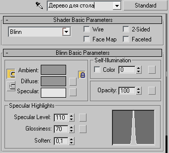
Now click on the button-box next to Diffuse and in the window Material / Map Browser select Bitmap. Next 3d max propose to choose a picture, we need an image texture of the tree, I will choose the standard texture 3d max BUBING_2.GIF, which is located in the folder C: \ Program Files \ Autodesk \ 3ds Max 2009 \ maps \ Wood (if you put 3d max folder by default).
In the window that appears, locate the Tiling and put out there so these values:

It will not stretch much texture (due to its double repetition of the coordinate V) on the table, making it not much more natural if you use a different texture, maybe you will have other values, you can of course do not change this setting and leave there is one.
Now click on Go to Parent:
to return to the parent material. Select all the objects that make up the table and click the Assign Material to Selection:
to apply the material to set up our table.
To see the changes in the viewport have to click on Show Map in Viewport:
It should be borne in mind that in the viewport, all materials presented in a simplified way to see how they will look at the scene really necessary to "render" by selecting the appropriate perspective to the table and press F9, then the scene will be "rendered" with default settings. The resulting image can be saved to your hard drive and use at their discretion. The default background color in render black, I usually put a white (for some reason I prefer, and use the image more easily.) The background color can be changed by pressing "8" key on your keyboard or by selecting the main menu Rendering → Environment. In the window that appears, change the setting Background.
The result is a "colored" table:
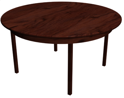
Some of you may be wondering - how to put texture 3d max, because we did not assign texture coordinates for the vertices of the table? The answer is quite simple.
The fact that the table consists of the standard primitives, and all the standard primitives texture coordinates are assigned by default, it is enough to tick Generate Mapping Coords (always installed by default) to create such an object:

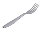
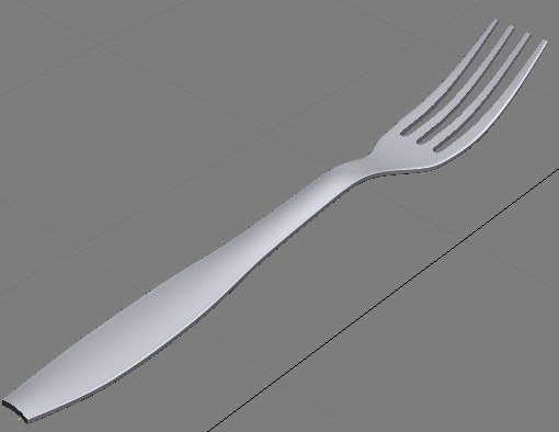
Oh and lastly, create a material made of metal for the last lesson on the fork.
Similarly, open the file with a fork (it can also be downloaded at the end of the previous lesson). Open the Material Editor. Create a Standard material with the type of shading Metal. Prostavte values as shown:

Note that the diffuse color of light gray, but with no large bluish, metallic sheen that will make more natural.
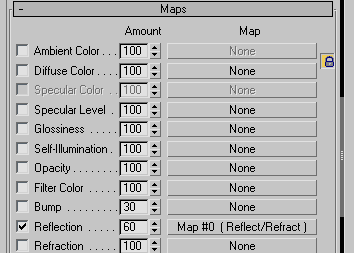
Next, go to the Maps rollout and click on next to Reflection (reflection) in the window that appears, select the card Reflect / Refract, the value next to the set 60 (which means that this option will operate at 60%),
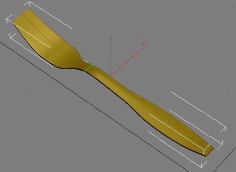
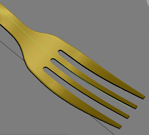
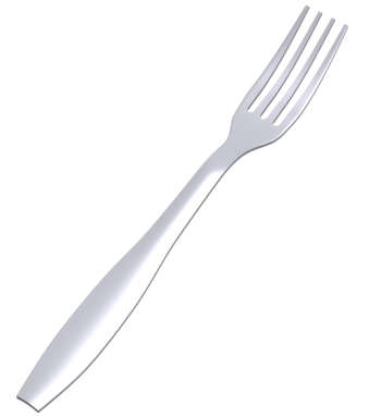
Assign the resulting material of the plug, the plug is turned with a metallic luster:
Well, that's probably it. All objects with used materials and textures as usual can be downloaded from the end of the lesson.