|
Part II: Creating three-dimensional model
Consider the basic steps of creating a simple Poly-model. Let's try to model Pluto the dog from the animated series <Adventures
of Mickey Mouse>. And how it will look finished
model:
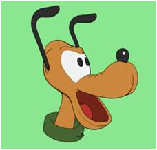
In Fig. An example of a model of Pluto.
Step 1: Drawings and
sketches, the order of
First of all, we need a regular flat sketch or a picture
of our little dog. It can be painted or printed on paper or in digital form to be
on the computer. In this picture we rely in
the simulation. It must be sufficiently
detailed and correctly reflect the shape of the object
In Fig. A sketch of Pluto.
Before you begin, always useful to understand the form,
making a few sketches or examined several images from different angles. Here we are the best fit simple clear images, since it is easier
to understand the shape of the object. It is very convenient to use,
for example, linear images are not painted.
   In Fig. 2 Sample images of Pluto workers. In Fig. 2 Sample images of Pluto workers.
Now let's define the order of work. In the simplest case (such as ours) modeling should be done from
general to specific, ie the first thing we need to
define the overall shape of our object, and then gradually to complicate it
by adding details.
Even the overall shape of the head of Pluto is quite
complex in terms of three-dimensional graphics. Therefore, our object should
be split into simpler parts. Let's create the first
direct's head, and then move on to the upper and lower jaws and neck.
In Fig. 3 to partition the elements
of design.
Step 2: Primitives and
Segments
Further, it is important to understand that net modeling
is to edit an existing
geometry, therefore,
we need it the most finished geometry - primitive.
Starting directly from the simulation is the selection and creation of the primitive. This choice is due to what, ultimately, seeks a form of the
object.
In Fig. A coliseum.
Usually, the simplified modeling can be summarized form
the majority of the objects so as to reduce it to one of the primitives. Most often, the most appropriate to start with would be Boxing,
cylinder or sphere, although professional trehmerschiki start with a polygon
(primitive Plane).
In Fig. Examples of two forms.
If the future shape of the object does not resemble any
of the entities, the creation of a simple solid geometry begins with the Box,
as it has a convenient grid, which clearly identifies each of the six areas
of modeling and, importantly, was originally closed.
In Fig. 3 Getting started.
The second important task is to select the required number of segments. Clear rules on this subject does not exist, there should be
enough to identify (if possible) overall shape of the object or the part that
we have is basic.
In Fig. 4 Determination of the
approximate number of segments.
In any case, the grid should not be too sparse or too
dense, as in the first case, we do not define the form and the second - it
takes too much time.
In Fig. 5 Choosing the optimal number
of segments.
Step 3: The general form
So, it's time to start working with the form. To object (NHL) has become an editable grid, select it and choose
from the context menu,Convert to: Convert to Editable Poly.
In Fig. 1 Getting Started with Edita
b le Poly.
From that moment, just modeling - let's try
edit the shape of our Box-level points. You can switch between the levels of editing, use the
appropriate icon in the scroll Selection. It is
important to note that you can work with both single and multiple points
simultaneously.
In Fig. Working with two points.
At this stage we need to locate a point as to
indicate the general shape of the head (base unit). It is convenient to use orthogonal
views - because they, unlike the bulk of
species, we see the true state of each point, and already known to you the
tools Select and Move  ,Select and Rotate ,Select and Rotate , Select and Uniform Scale , Select and Uniform Scale  
In Fig. 3 The formation of the general form of the head.
Using this point when dealing with the general form of
the grid is not required, but it is the most accurate and convenient way, and
do so made. You will see this by trying to work with other types of
subobjects.
Notice how the same operation on different sub-objects
lead to different changes in the grid: 
|
|
|
As you can see, rotate or scale of points is based
on a single, averaged over the cente
|
In the case of polygons and the edges of each
sub-object will be rotated around its axis
|
At this stage, the first problems may arise. Let's say you are missing a number of points to make the bend in
a certain area of the grid.To do this, we can create in this place an
additional section, using the tool Slice Plane (section plane) from the scroll Edit Geometry.
In Fig. 4 Select the cutting plane.
Then put the plane appeared at the place where you want
to create a new series of points, and then click Slice in the same scroll. At the intersections of the cutting plane with the edges of the
grid points will be created, which in turn will be connected by edges.
In Fig. 5 Setting the cutting plane.
* The fact that we create using the Slice section, means
that we are dissecting the entire
model at once, a
solid number of edges.
Of course, you may encounter as a shortage or an excess
of subobjects. Deleting subobjects to Editable Poly in two ways:
- The physical removal of a fragment of the object with
subobjects;
- Removal of the sub grid.
In the first case, pressing the <Delete> key on your keyboard, you delete the
selected sub-objects, together with the planes (polygons) to which they
belong, in other
words, the surface is formed in the hole. The result of such removal
for different types of subobjects will also be different. For example, if we remove the point which belongs to the four
polygons, then all four of the landfill is also deleted automatically at the
same time, we can remove the ground, without hurting any one point.
In Fig. 6 Example of deleting a point
and polygon.
The second method is applicable only to remove the points
and edges, and its essence lies in the fact that we remove the sub-objects
from the grid, without violating the integrity of the surface. Obviously, the shape of the object at the same time can vary,
for example, some landfills may merge into one. To delete a subobject or subobjects of the group grid, first
select them and then use the Remove the
roll from the Edit Vertices / Edit Edges.
In Fig. 7 Removal Tool.
In Fig. 8 The result of the deletion.
Removal of the sub grid is on the following principle:
- The top (point) is removed along with all the ribs to
which it belongs;
- An edge is removed together with the point if this
point belongs only to this edge.
Step 4: Roll
Finally, the head took the necessary form, and we can
begin to create in the upper jaw, for this position ranges in front of the
head in the form of the cross section in the place shown in the figure.
In Fig. 1 Pre-extrusion.
Now select all the polygons that make up this section
and, using the command Extrude (squeezing), a little squeeze this section forward. Note that using Extrude created a new section, combined with the previous one, but in our model, the number of subobjects.
In Fig. 2 Tool extrusion.
In Fig. 3 Result extrusion.
Next <dial form> continue squeezing until then,
until you get the number of sections, sufficient to indicate the general
shape. In the case of an error at this stage is also convenient to
use Slice tools already
considered, and Remove.
In Fig. 4 Select the segments.
Watch for a uniform grid, we need to be based on the
level of detail with which the work originally. In other words, the general
form of the density of the grid should be about the same.
In Fig. Wrong choice of five
segments.
Despite the fact that we are working with a specific
object, the above described approach is applicable to all models, which are
clearly visible connection.
In Fig. 6 Example for a complex
model.
An important feature of this approach is that we add
sub-objects, building up the form, not the form itself (as in the case
of Slice). Thus, we do not change our position is spaced points.
Now place the point of appearing to get an upper jaw. At this stage, does not require great precision, but the grid must be organized so that later it was
convenient to model the details. For example, in this case, we
need to have a series of points in the field of folds on the nose of Pluto. Here's what happened in the end:
In Fig. 7 The choice of points.
Similarly, let us create the lower jaw. Note that the orthogonal modes Top / Bottom (top / bottom) of the upper jaw
prevents us to select and edit the lower jaw. In such cases, sub trehmerschiki are hiding.
In Fig. 8 The result of squeezing the
lower jaw.
Let <hide> the upper jaw, for this select all of
the polygons, and then click Hide Selected (to hide the selection) in the
rollout, Edit Geometry, as you may have
guessed Unhide All button is used to
return to the screen the hidden sub-objects selected level.
In Fig. 9 tools to hide the isolated
segments.
In Fig. 10 results.
Now create the lower jaw in the same way that created the
top. Then again, with the Extrude tool squeeze the neck, or, in general,
all other parts of your model.
In Fig. 11 Modelling of the lower
jaw.
In Fig. 12 Simulation of the neck.
Finally, before detailed, domodeliruyte basic volumes and
specify the proportion of your mesh.
In Fig. 13 The resulting crude model
of Pluto.
Step 5: Detailing
Thus, the overall shape is ready, start detailing. You probably already noticed that our object is symmetrical, so
in order to ease the task of sufficient detail to simulate only one half, and
then flip to another.
In Fig. A sketch of Pluto.
Remove half of your model exactly in the axis of
symmetry, then select the modifier Symmetry * (symmetry) of its stack. Designate the axis and the direction so as to again see the
entire object. Now all the changes that we
will produce in one half, Symmetry will automatically display in another.
In Fig. 2 Using the tool Symmetry.
* In older versions of the program for this purpose was a
modifier of Mirror (mirror).
Come back from the simple to the complex, and primarily
simulate wrinkles on the nose. Obviously, we do not have
enough points to make a bulge. We could use the cutting plane,
but it's not very convenient, because then we would remove the extra
sub-objects in the lower jaw.
In Fig. 3 Example of unnecessary
steps Slice.
Instead, we choose some edge in areas where need
additional rows of dots and connect them to the middle of using the Connect(connection) rollout Edit Edges. Connect to the Slice advantage
is that we do not have to create a vicious series of sub-objects, you can
simply connect the individual, we need an edge or point. Now pull the newly created vertices, so that the folds were
obtained.
In Fig. 4 Tool Connect.
In Fig. 5 The simulation results of
the folds.
There are cases when the edges must be added directly by
drawing them on the grid. For these purposes, is a
tool Cut (Cut) from the
scroll Edit Geometry.
In Fig. 6 cutting tool.
Create thus the lower contour of the lips and oral
cavity, in the place where you clicked Cut will
put a new one and connect it with the previous one. If you cut should be possible to rely on existing points or
edges, so as not to create unnecessary extra sub.
In Fig. 7 Path Selection.
Now select the polygons above the cut contour, squeeze
them with the Extrude and by moving the
point model the lower lip.
In Fig. 8 Roll the circuit.
Similarly, the oral cavity create
In Fig. 9 Establishment of the oral
cavity.
Do not forget to remove the extra point near the corner
of his mouth. Removal of entire grid nodes without losing connection - a very
complicated process, so closely spaced points can be <weld> using the
scroll Collapse Edit
Geometry, which
reduces the selected sub-objects at one point.
In Fig. Welding of 10 points.
In Fig. 11 The result of the welding.
As you can see the same problem in Editable Poly can be
solved in different ways. You can work as one, and in
several places at once form and order of each may be his. You need to learn to find the best methods of editing a form in
each individual situation.
Likewise, combining different ways of working with
subobjects prepare the grid for the other parts: eyes, eyebrows, back of the
head and base of the ear. Make a depression in the
lower jaw.
In Fig. 12 Simulation of the ear.
In Fig. 13 Simulation of the occiput.
In Fig. 14 Simulation of the
eyebrows.
In Fig. 15 Simulation of the eye.
Step 5: Smoothing
Once all the parts are ready, we will see that the
resulting shape, and even remotely resembles the original, but it still seems
too broad and rough. It's time to smooth out all irregularities, using modifier Mesh Smooth. Applying it, place in the
book value of Subdivision
Amount Iterations = 3, and look what happened.
In Fig. The result is a smoothing.
* Attention! Increasing the number of
iterations may hang the computer, due to the fact that, after smoothing the
number of planes in the grid will increase by several times.
Mesh
Smooth modifier
works as follows: the thinner the grid, the greater the radius of
curvature. This is explained by the fact that the modifier in the
calculation is based on the size of the landfill.
In Fig. 2 Examples of anti-aliasing.
Step 6: Working with a
smoothed form
In some places in the folds of our model should be
clearly sharper. Due to specific modifiers Mesh Smooth, for sharp bends of sufficient seal the
grid in the right places.
In Fig. 1 Definition of problem
areas.
For such a local infill easy to use tool Chamfer (bevel) of the rollout Edit Vertices / Edit Edges. Chamfer applied to the points
and edges, and works as follows:
In Fig. Two bevel tool.
In Fig. 3 Result of the tool Chamfer.
In those places where the use Chamfer difficult you can use the familiar
instrument of Cut. Seal the grid in places where they should be crisp folds or
creases.
In Fig. 4 The result of the Cut.
Do not forget that at this stage, we work closely
with Mesh Smooth, so you need to
periodically return to the top level of the modifier stack and check what it
looks like the shape after smoothing.
There are situations where the model between the parts
must be perfectly clear border, but as you can see, Mesh Smooth modifier default smooths the entire
form as a whole, and its application to individual polygons leads to
deterioration of the grid. To solve this problem, use
the method of smoothing
groups.
In Fig. 5 Determination of the
boundaries.
The method consists in the fact that we celebrate the
individual polygons, thereby forming a group, smoothing the boundary between
the polygons that will not be made, in other words, joining groups in places
we will see a sharp break in the form. For the separation of groups
is the section Smoothing Groups (smoothing groups) scroll Polygon Properties.
In Fig. Group of six anti-aliasing.
In Fig. 7 The result of smoothing
groups.
When working with smoothing groups should be very
careful, because apparently they are poorly distinguishable, except for the
appearance in the form of new landfills, they are assigned automatically, so
before you start, make sure that the distinction belongs to the whole grid is
the same group. In practice this is done as follows: assign the whole head first
group of anti-aliasing, and the polygons that form the eye, the second one,
go to Options and check the Mesh Smooth there Smoothing Groups, to enable anti-aliasing in groups.
Step 7: The missing part
Once you have modeled the most complex grid (in our case
directly to the head) begin to create the other parts. First, select and create the most significant (nose, ears,
eyes). Then move on to less important and visible
(tongue, collar).
In Fig. A list of the missing parts
for model Pluto.
Do not forget about symmetry! You do not need to simulate each ear separately!
Step 8: Combine parts of
the model
So to create a form of the head of Pluto, as if finished,
but it consists of separate parts, each of which is, in essence, is an
independent model. We also need to output a single-piece model of the head. To associate all the parts into a single object, use the Attachcommand of the rollout Edit Geometry.
In Fig. An instrument of accession.
It is important to note that after you bind all the parts
into a single object, they do not completely lose its independence. After the command Attach new
mesh included in the model as an element hotel. You can select items on the
level of editing Element, and, if necessary, again to disconnect them using
the scroll Detach Edit Geometry.
In Fig. 2 Tool disconnection.
In Fig. 3 Result of the instrument
Attach.
In the last step can already be applied to your model
materials, lighting options and make the necessary imaging angle.
In Fig. 4 The result of the above
model.
Part III: Key error
And finally, before issuing a job, let's look at the main
errors occurring during the simulation. It is not hard to guess that
they are all connected with the organization of the grid.
The first mistake - a different density of the grid in places with
the same detail. In this case, obviously, it will be difficult to find the
necessary number of iterations in the smoothing. In addition, a grid is more difficult and longer to edit.
The following error - this is a nonuniform grid - in which the
distance between the rows of dots is illogical and random orientation of the
sub. Since it is simply inconvenient to operate. Do not run your screen! It is always better to spend
the time and level
It is undesirable to leave the grid and the triangles <asterisk> - a few triangles
with common vertex. When smoothing such elements pull together on a grid, forming a
groove, and if the use of triangles in particular cases is acceptable, then
the appearance of <asterisk> should be avoided.
The grid is considered rude, if it contains <broken> polygons or polygons with more
than four vertices. The software automatically splits such polygons into triangular
and quadrangular, and does it quite arbitrary, so in places where there are
subobjects you lose control over the form.
|


